
I’ve done a couple of KFest presentations about setting gains in new systems and suggested that all of this scoping and 0dB sine waves aren’t all that useful in a system that includes a DSP and some amps or some amps with DSP.
One of the topics in those has been a explanation of how this works inside a DSP, because this is different than an old school system comprised of a long chain of analog processors that each have an input sensitivity control. There is a constant suggestion that you want all the gain at the beginning of the chain so you can have your amp gains “lower”. In general, reducing the gain at the amplifier is a good idea, but attempting to put a bunch of gain at the front is not. If you’re using the analog inputs to your DSP, the input sensitivity control has ONE function and it’s an important one–setting the input voltage so you don’t clip the A/D convertor after the input preamp.
That’s it.
If you clip that, then the rest of the signal is clipped and digital distortion doesn’t sound like analog distortion. It sounds like broken speakers. Your DSP may have potentiometers that you adjust with a screwdriver to do this. Your DSP may have electronic potentiometers that do this and that you can set in the software. Your DSP may not have any adjustments and the attenuation may be fixed at the minimum sensitivity. Lots of systems that include Audiofrog speakers also include Helix DSPs. I haven’t checked all of them, but at least one uses these electronic pots. The voltage RANGE of the inputs is set by some jumpers on the PCB. The fine adjustment of those potentiometers is set in the software. This is a really cool feature, but only if you know how this works. This has to be set correctly. If you have a 4V radio, then this has to be set up for 4V. If you set it for 1V, then you allow 12dB of clipping on the input to the A/D convertor. Once that happens, nothing you do with any amplifier channel level, EQ or input level control in the DSP–in the mixer in which you select 50%, 100% or whatever– will remove this distortion because it’s been converted to digital in the A/D convertor.
You can attenuate all you want in the DSP and never get rid of this because it’s now part of the music and it’s your fault. In the input mixer, you select the DIGITAL signal to mix together. 50% of one channel and 50% of another channel is 100% and 100% is the same as 0dB. 0dB is as loud as the digital signal can be before the digital signal clips. So, if you have a 4V radio and you set the analog input level at 4V and then you set all of the input levels at 100% and you set all of the output levels at 100%, that’s all you get. There’s no more.
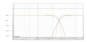
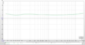
So, in this case, IF you boost in the EQ AND the signal at the frequency at which you’ve boosted reaches 4V on the output of the radio, you get distortion. The only place in the frequency response where this is likely to happen is in the bass (see the tech tip on the Audiofrog site about pink noise and white noise). If the bass distorts the signal in the DIGITAL chain in the DSP, you may only hear this distortion in the subwoofer. But, if the bass causes clipping BEFORE the crossovers in the DSP or BEFORE THE DSP inside the processor (in the A/D convertor), then you’ll hear the distortion in all of the channels.
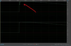
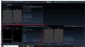
Here is an example. I haven’t confirmed that this is the problem, because I haven’t heard back from the troubleshooter. But, the claim is that there are bad GB25s. Here’s what I found. The radio is 5V. The jumpers haven’t been moved. But the level adjustment in the processor for the analog input is set to 1V. The RADIO doesn’t clip at volume 32 out of 40, but guess what…There’s 12dB of distortion now built in to the DSP because it gets created in the A/D convertor. This slider should be moved to 4V (to the left). Or, if the radio is ACTUALLY 5V, then it should be set to a different range (2-8V) and the slider should be set to 5V.
This is not the place for gain overlap. It never was with the old scope method and it surely isn’t now, either.
It’s really important to read the owner’s manual to see how your processor works. It’s important to understand how this works. A scope and a sine wave or a DD-1 and one of two sine waves is not a substitute for reading the manual and understanding what it indicates. And, it’s important that there IS a suitable owner’s manual for a DSP because it isn’t the speaker guy’s job to read your owner’s manual and tech support your DSP and to send you new speakers over and over and over because it “has to be the speakers”. It is the speaker guy’s job to confirm that the speakers are OK and he may offer to check them if you send them back. Three pairs of speakers that were thoroughly checked at the factory before being put in the box are bad? or…”Maybe I’ve made a mistake somewhere in the setup of a device I don’t understand and for which I cannot be bothered to read the manual?”
I’m going with option #2.