
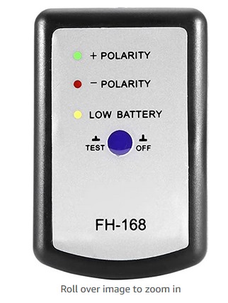
Fyi for those of you who have this polarity tester: the tester works fine, but pulses on the CD are not long enough to allow you to get a polarity reading for midbass speakers or subwoofers through low pass filters. My suspicion is that either the people who made this and the CD imagined the use would be in checking the polarity of full range speakers and intentionally made the triangle really short in order to check the polarity of the high frequency driver, since home speakers often have passive crossovers and the placement on the baffle and the slope and alignment of the crossover might necessitate a polarity reversal on the mid. This tester WILL work with the polarity track on the Audiofrog CD, but it will just blink green repeatedly for in phase and red repeatedly for out of phase. There’s no three green and one red because the pulses on the Audiofrog CD are all forward (positive)-going.
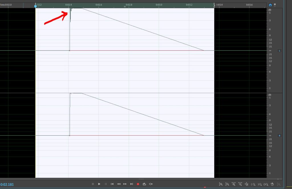
OK. Here’s a little more info about this speaker polarity test and the difference between the signals on the various CDs. Look closely at the graphs to see what happens. Here’s the wave form. This is from the Audiofrog CD that comes with the mic kit. You’ll probably notice first that it looks like a right triangle and the entire waveform is ABOVE zero. If the mic in the little box sees this, it will light the green light–indicating forward motion (toward the microphone). If the polarity is incorrect, then the speaker would move rearward initially and that would light the red light for incorrect polarity. The second thing is that it’s about 9mS long. A 20 Hz wave is 50mS long (about). So this is enough to provide some signal at really low frequencies. Now, if we look at this triangle, the slope of the initial VERTICAL line IS high frequency. The high frequency sine wave is STEEPER than the low frequency sine wave. Because the low frequency wave is LONGER, the length of the triangle captures the bass. WHAAAAAAAAA?
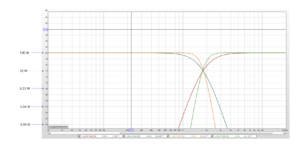
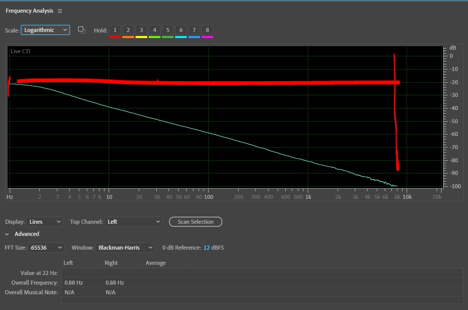
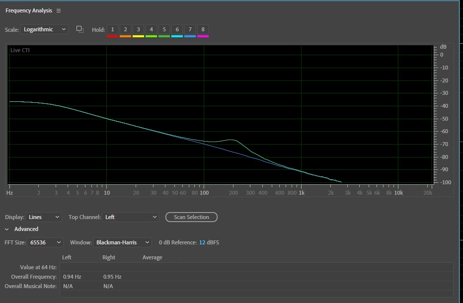
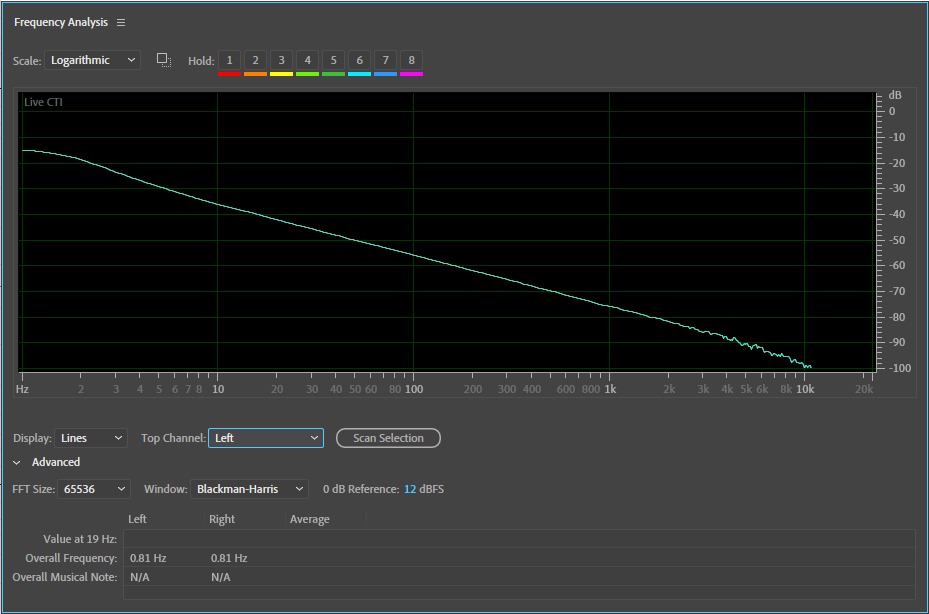
OK…If you’re still trying to follow this, here’s a graph of the frequency response of the signal. This is NOT an RTA, This is a spectrum display. If it was an RTA, this would show a frequency response that’s closer to flat.That really doesn’t matter. What we’re looking for is what frequencies are included–because we’re trying to check the polarity of speakers that play different parts of the signal. If there’s no bass, then we can’t check a subwoofer. If there’s no high frequency, then we cant check a tweeter. This is ESPECIALLY true if our system includes CROSSOVERS.This goes from 0 Hz to about 10kHz.
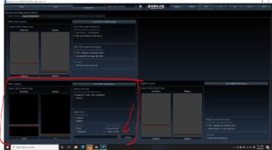
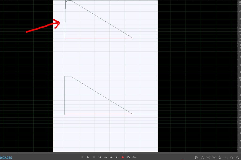
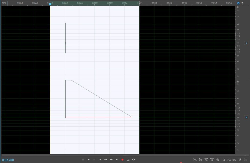
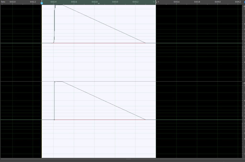
Now let’s apply some crossovers to this signal as if we had those in our system.Here’s what happens when we have a 60Hz low pass filter.I’ve applied the filter only to the left channel (the one on top) so we’ll be able to easily compare.Remember when I said that high frequencies ARE the beginning of the triangle? Now we have a slope at the beginning rather than a VERTICAL line.
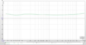
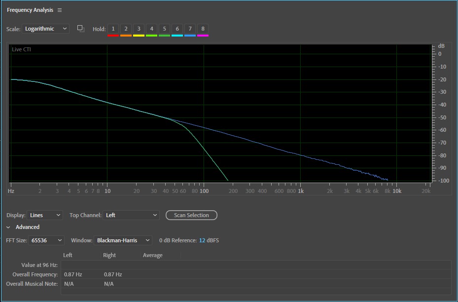
OK. Let’s see what our crossover did to the frequency response.
Exactly what we suspected it might do…because it’s a LOW PASS filter:
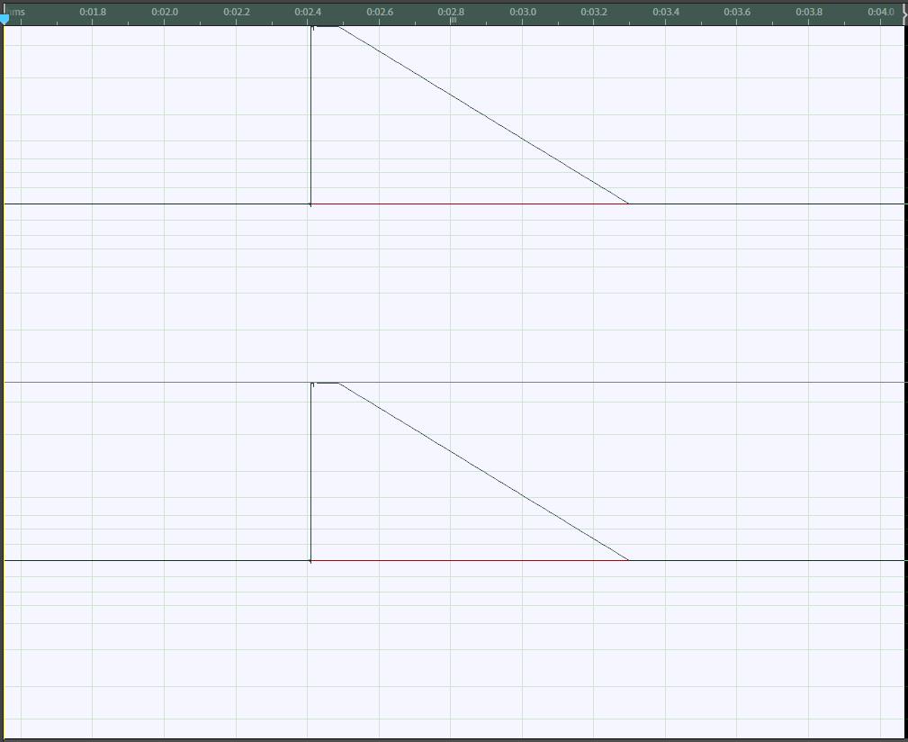
Let’s remove that and insert a high pass filter instead.Now the tail (the bass) is completely gone:
Let’s look at the frequency response. I used a 4th order (24dB/oct) high pass at 600 Hz:
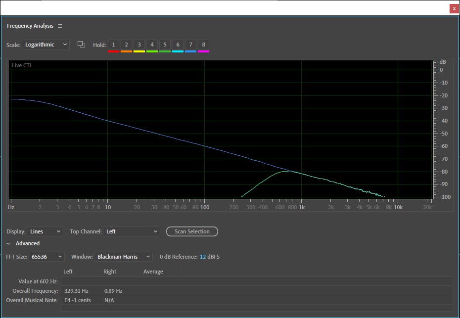
Exactly what we expect to see.
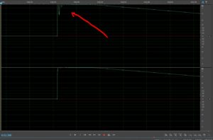
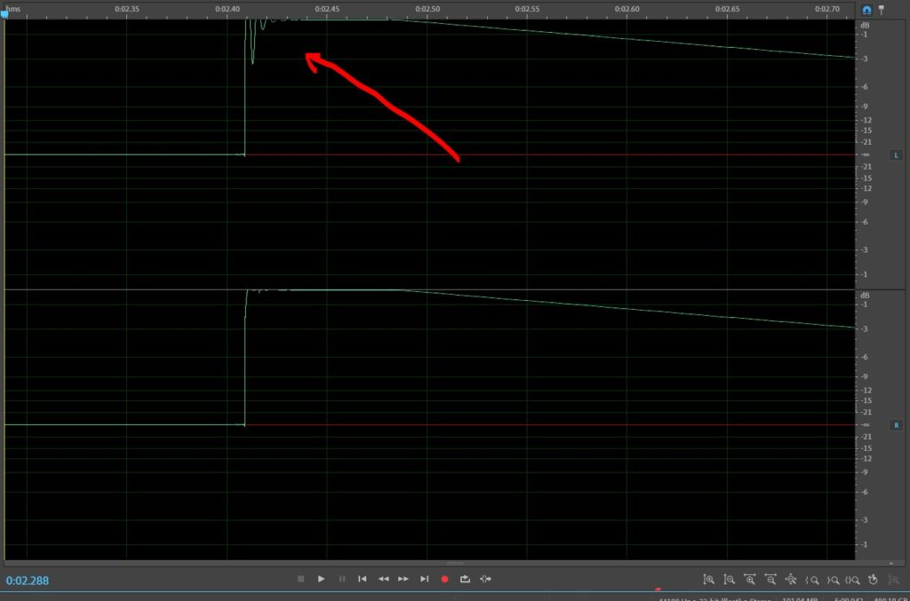
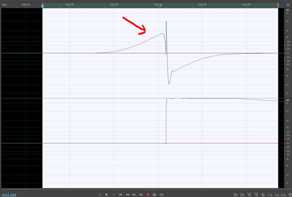
Now let’s zoom in on the waveform.
OK. This is zoomed in A LOT. So much that you can’t really see the one on the right channel (the one to which we didn’t apply a high pass filter).Notice that the ENTIRE waveform is contained in about a third of a mS:
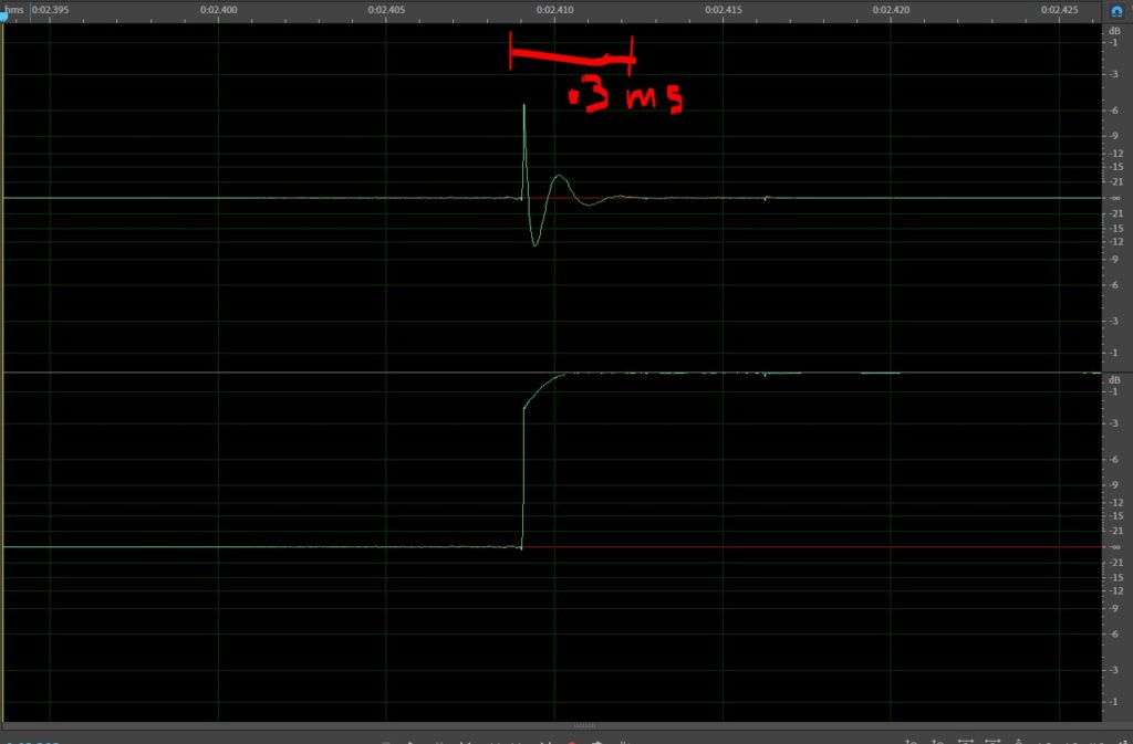
Hey, WAIT A MINUTE! Now some of the waveform is BELOW zero. How can that be?
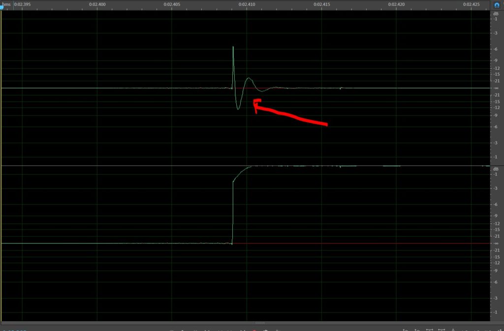
Because crossovers shift phase. Notice that the initial peak is POSITIVE and LATER, there’s some stuff “out of phase”.Remember how this works and what this display tells you. Things that happen first are “in phase” and things that happen later aren’t. This not an error. The phase shift in a crossover isn’t a mistake. It’s how crossovers work. If they were perfectly in phase (no phase shift at all), the only ones that would sum flat would be Linkwitz Riley crossovers with orders that are positive multiples of 4. 4th, 8th and so on and so forth.All other crossover alignments HAVE to be a certain degree out of phase to work correctly.First order are 90 degrees out. Second order are 180 degrees out (so one side has to have its polarity reversed). Third order are 270 degrees out of phase.This is intentional. When you find a passive crossover that changes polarity, this isn’t a mistake. This is how crossovers work.
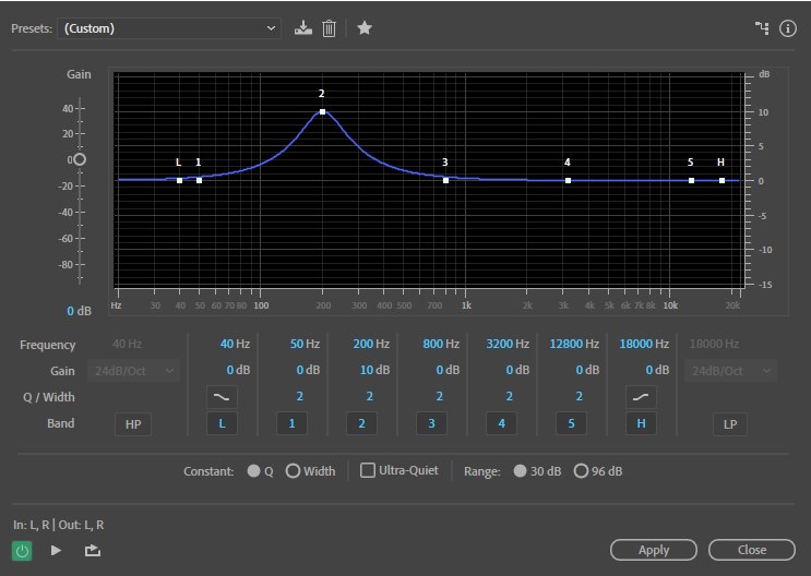
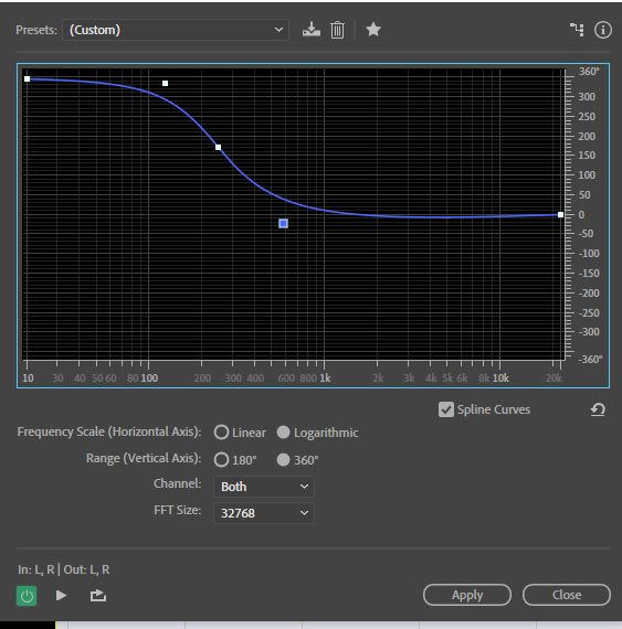
What about EQ? What does it do to our waveform?Let’s boost 200 Hz by 10dB:
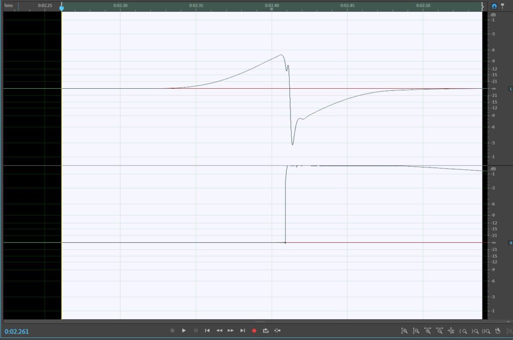
Here’s the waveform. Some “wiggles at the beginning”:
Here it is zoomed:

Here it is zoomed:
And here’s the frequency response:
So, with the right track, we should be able to check the polarity of each of the speakers.I t’s helpful to turn off the REST of the speakers to avoid some unwanted contribution from the other speakers.
Oops. One last thing. What happens when there’s an all pass filter–like in a factory system?Here I’ve approximated a second order all pass filter. Let’s see what it does.
Here’s what we have now.
Let’s check the frequency response:
So, through a simple second order APF, this will work fine. You’ll read the correct polarity.
What about a first order APF(all pass filter)? That changes the polarity of frequencies below the filter frequency.Here’s what that looks like:
I’m not sure what this little polarity detector will do with this. Maybe an empirical test would be helpful.
What if it was a midbass speaker and it was crossed at 300Hz AND included this 1st order APF? Then it would look like this. I’m guessing this would be a green light rather than red.
So, I think the moral of the story here is that the signal that’s on the CD matters.For what we do, it’s really important that it contains all the frequencies our system will play so we can test each one that’s dedicated to a specific part of the signal.I think that the signal on the CD that comes with the inexpensive tester is purposefully designed to identify the polarity of the tweeter accurately so the left and right full range home speakers can be checked.
If you’re a pro or if you can budget a little more that $20 for a tester, I recommend this one. It has speaker level and preamp outputs and it will also generate the signal or read a signal from a USB: https://www.mobilesolutions-usa.com/product…/pt-9aplus-kit