Few specs are as poorly understood as amplifier damping factor. The suggestion in the spec is that the closer to a short circuit the amplifier’s output appears to the speaker, the better the amplifier’s ability to control the unwanted motion of the cone when the signal stops.
Is this true? Well, as with many specs, sort of. Kinda. The fact is that the importance of the spec is wildly overstated. While it is a good idea to design and build an amplifier with low output impedance, there’s a practical limit to what is required to achieve good performance.
The formula for damping factor is simple—it’s the speakers nominal impedance (which should give one pause) divided by the amplifier’s output impedance.
Yeah, so what’s wrong with that?
First, we have to look at how the speaker actually works. Although the spec is attributed to the amplifier, the equation is one for a system—the speaker is included in the equation, too.
If the speaker was a simple capacitor or inductor, then the equation would work and the amplifier’s output impedance would create its own path for current to flow from the inductor or the capacitor. The lower the output impedance the more current would flow and the faster the stored energy would be exhausted.
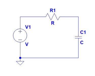
In the simple circuit below, this would work just fine. The voltage source would charge the capacitor and the output impedance (R1) would regulate the flow of current to ground to discharge the cap when the voltage source was turned off. If this was a source of AC voltage, then the cap would charge and discharge as the voltage changed direction but the same thing would happen when he voltage source was turned off. The stored energy would be dissipated via current flowing through the resistor. The smaller the resistor the greater the current flow and the faster the energy would be dissipated.
OK, so why doesn’t this work for a speaker?
A speaker isn’t a simple energy storage device like a capacitor or an inductor. Below is a simple electrical model of a speaker. There are more complex models that better represent what’s actually involved, but this one will suffice for this explanation.
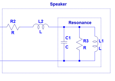
In the model above, R2 is the DC resistance of the speaker’s voice coil, which is determined by the length and gauge of the wire in the coil. L2 is the voice coil’s inductance which is determined by the number of windings, or turns, around the voice coil’s former. The combination of C1, R3 and L1 is the impedance peak at resonance and it’s determined by the compliance of the spider, and the mass of the moving parts and loss in the resonant system.
Before we move on, we should probably explain the resonant system in a bit more detail, since that’s the energy storage device and the one that the amplifier’s output impedance supposedly affects.
A resonant system is simply a system that continues to move when it’s set in motion. When the speaker’s cone is moved, the mass of the moving cone and the speaker’s suspension don’t come to rest immediately. It’s just like a mass suspended from a spring. If you pull down on the mass and let it go, the system will move up and down and up and down until it eventually comes to rest.
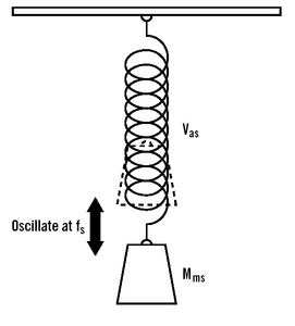
In our speaker, the mass is Mms (one of the Thiele and Small parameters), Vas (another of the parameters) is the compliance of the suspension and Fs (a third parameter) is the frequency at which the continued movement occurs.
Because the voice coil is suspended inside a magnetic field, the continued movement of the assembly generates a voltage (just like in the generator or alternator in your car) and that voltage causes a current to flow, which continues to move the cone back and forth.
So, the idea behind damping factor is that if the amplifier’s output looks like a short circuit (or as close as possible to a short circuit), the voltage that’s generated in the coil will cause current to flow through the output impedance and the more current that flows, the faster the energy will be dissipated and the quicker the speaker will come to rest.
Ok, seems simple enough. Let’s add the amplifier to our speaker model.
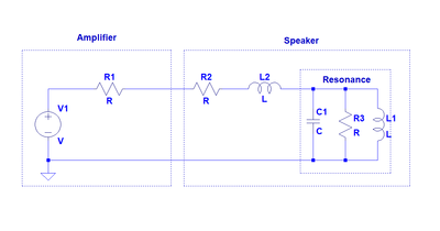
Now, we have the amplifier, which is an AC voltage source and the amplifier’s output impedance, which is R1 in our model.
So, when we set the speaker in motion, energy is stored in the resonance and when the signal from the amplifier goes away, current flows to ground through the rest of the circuit. Let’s say that this is a great amplifier with a damping factor of 1000 at 4 ohms and we have a 4 ohm speaker. That means that the amplifier’s output impedance is 0.004 Ω and our speaker’s nominal impedance is 4 ohms. To make this simple, we’ll say that the speaker coil’s DC resistance (R2) is also 4 Ω.
So, the current that flows passes through the speaker’s DC resistance (R2), which is 4 ohms, and then through the amplifier’s output impedance (R1) which is 0.004 Ω, and through the voice coil’s inductance, which doesn’t have a resistive component, so we can ignore that.
So, in order to determine how much current flows, we need to determine the total series resistance. For resistors in series, the total is simply the sum of the resistors. So, the total resistance is 4.004 Ω.
To make things easy, let’s say that 10 volts is generated in the coil. By Ohm’s law, current is equal to voltage divided by resistance, so 10/4.004 = 2.498. 2.498 amps of current will flow from the resonance to dissipate the energy that’s stored.
Since current flow is constant in a series circuit, in order to determine which of the components (the speaker’s DCR or the amplifier’s output impedance) has the most influence over the flow of current, we can simply determine the voltage drop across each of the resistors in our model. The sum of the voltage drops is proportionate to the value of each resistor, so
If we solve for x, we’ll get 2.4975.
2.4975 x 4 = 9.99V.
2.4975 x .004 = .00999V.
Hmmm…so, it appears that the speaker’s DCR is what regulates the flow of current—it has 1000 times more influence on damping than the amplifier’s output impedance has.
What if we made an even better amplifier with an output impedance of .0004 ohms? Then, the speaker’s DCR would have 10,000 times the influence on circuit damping.
As it turns out, we already have a Thiele and Small parameter that indicates damping in the speaker: Qts.
In a speaker, Qts is a combination of the electrical Q and the mechanical Q and the formula for Qts is:
Since the amplifier’s output impedance is in series with the speaker’s DCR, we can include it in the formula for Qes:
So, if we work these equations for a speaker that has a Qts of .707, we’ll see that an amplifier with a damping factor of 1000 will raise the Q to 0.708. That’s not an audible increase in Q and it isn’t an improvement in system damping. In fact, any amplifier output impedance is a degradation in system damping.
So, just how low does the output impedance need to be to not screw up the transient response of our speaker too much?
Thanks to Richard Pierce, who’s already done the math, we have a table that indicates the effect of output impedance on damping and I’ve included it here.
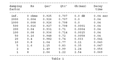
In this table, Rs is the amplifier’s output impedance (he used an 8 ohm speaker for this). The Qtc represents the damping of the circuit. Gh is the amount of ripple in the speaker’s response that’s created by the amplifier’s output impedance. And decay time is the time it takes for the speaker to return to rest after the signal goes away.
If we look carefully at the table and focus on the Gh column, it’s pretty obvious that at really high damping factor values, there’s no audible change in the frequency response of the system. Even a damping factor of 20 only creates three hundredths of a decibel in ripple. We can’t hear that. At a value of 10, a ripple of a tenth of a dB is caused by the output impedance of the amplifier. The audibility of a tenth of a decibel is questionable. Maybe…just maybe…we can hear that.
So, it’s reasonable to assert that an amplifier with a damping factor of greater than 10 is indistinguishable in terms of system damping (cone control) from an amplifier with a damping factor of 10,000.
Good luck even finding an amplifier with a damping factor of 10.
There is a real benefit in low output impedance. We’ll save that one for another tech tip. Rest assured, however that nearly every amplifier available for your car has sufficiently low output impedance. When you choose an amplifier, focus on getting the right amount of power and on the features you need. Don’t be swayed by claims of superior cone control—that’s a myth.
References: “DAMPING FACTOR: EFFECTS ON SYSTEM RESPONSE: A TECHNICAL ANALYSIS”, Dick Pierce, Professional Audio Development


