
After reading a lot of Facebook posts about time alignment settings and after a couple of tech support calls last week, I decided I’d Google “how to set time alignment”. Apparently there are a million different perspectives about this, what one can reasonably expect to achieve and how this actually works.
Before we can talk about how to use time alignment, I think it might be helpful to understand how it works inside your DSP. First, a little review of digital audio basics. There’s a previous topic here that explains this in more detail.
First, digital audio signals are a series of samples. When an analog waveform is converted into a digital signal, the analog waveform is sampled. The sample rate of the convertor determines the number of times per second that the signal is described by a single sample. In layman’s terms, that means that every so often, the convertor looks at the signal and converts it into piece of information that describes the level of the signal at that instant.
The Nyquist Theorem (thanks Harry Nyquist) says that in order to be able to perfectly recreate a periodic signal, we need two points to describe the signal. For audio signals, we need to be able to perfectly recreate a 20kHz signal. So, we need two samples to recreate that, so we need a sample rate of at least 40kHz. For a CD, the sample rate is 44.1kHz. That gives us a little margin for applying a low pass filter to the signal while maintaining flat response to 20kHz.
The Nyquist Theorem works kind of like a couple of rules we learned in geometry class. Two points in space defines a line and three points defines a plane. For any two points in space, there can be only one straight line drawn between them. For a periodic signal (a sine wave), the same thing is true. There can be only one sine wave drawn between two points. So, if we know two points, we can recreate the sine wave perfectly.
Here’s how that works. Below is a picture of a 20kHz sine wave. The dots are samples. This program knows to draw a sine wave between each pair of points, and that defines the waveform.

Here is a picture of a 100Hz wave. Just like the picture above, each dot represents a sample. The sample rate of this file is 44.1k, so there are a lot more samples in the much longer 100Hz wave than in the really short 20kHz wave. The additional samples don’t add any precision to the representation of the sine wave, just like additional points on a line in space don’t change the line.

Each of the samples contain information (a series of ones and zeroes) that define the vertical position (the level) of the sine wave. When we sample a more complex waveform, the same rules apply. Below is the waveform of a piece of music (Stretching out in Bootsy’s Rubber Band by Bootsy Collins). Each sample represents the level of the signal at an instant and interpolating a line between all of the dots recreates the waveform below 20kHz perfectly.

Just like the digital signal on the CD, our DSP also has a sample rate. Lots of processors sample at 48kHz, so we’ll use that as an example, for now. That means that every 1/48,000 of a second, the DSP records the level of the signal. Then, our DSP lets us change two things: 1) the level of the signal for each sample, and 2) the timing of the sample. Level changes are how we add crossovers and equalization. Changing the time is how we adjust time alignment. I’m going to refer to time alignment as “delay” from here on out.
Inside the DSP chip in our processor, there’s some storage—some memory–, which is called a buffer. Besides using some math to change the level of the samples, we can also use our DSP to tell the buffer to hold onto the samples and then release them later, kind of like in the diagram below.

Because our DSP also has a sample rate, we can ask the buffer to hold the sample in as small as one sample increments because that’s how often the DSP executes an operation. For a DSP that samples at 48kHz, we can ask the buffer to hold all the samples that pass through it for 1/48,000 of a second, 2/48,000 of a second, 3/48,000 of a second and so on and so forth until we reach the maximum amount of data that can be stored in the buffer. The amount of storage space determines the maximum length of time the samples can be stored and the sample rate determines the minimum amount of time for which a sample can be stored. That minimum determines the resolution of the delay settings that are available.
Since sound travels at a particular speed, we can convert that time into distance. If one sample is 1/48,000 seconds then one sample at 48kHz is equal to 0.02 milliseconds which is equal to 0.2858 inches. So, if our DSP samples at 48kHz, we can delay the signal in increments of about ¼” to compensate for one speaker being farther away than another one.
So, why does this matter?
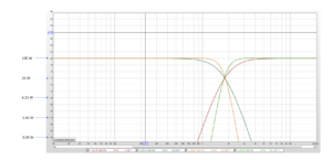
There are a couple of reasons. One, is that classic crossover filters that we use to divide the audio signal into bands that can be reproduced by tweeters, midranges and subwoofers are designed based on the assumption that the sound from each of the speakers arrives at the listening position or the microphone at the same time. The alignment of the filters (Butterworth, Linkwitz-Riley and Bessel, for example) define a slope and a phase relationship between the high pass and low pass sections so that when we hear the two of them together, the response we hear matches the intended response.
The second reason is that stereo recordings, designed to be played back over two channels are designed to be played back in an arrangement in which the sound of the two speakers arrives at the listening position in phase. Since phase and time are related, we can ensure this relationship by placing the speakers the same distance from the listener.

This is easy at home, but not so easy in a car because the driver’s seat is closer to one speaker than the other. We can fix this for one seat by asking the buffer in our DSP to hold onto the samples in the left channel and to release them so that the sound that comes from the left speaker arrives at the same time that the sound from our right speaker arrives. That puts the speakers in phase at the listening position and we hear an image of instruments and vocalists in between the two speakers. When it’s correct, it sounds great. When it isn’t correct, we don’t hear a center image. We hear the much of what should be spread out between the speakers at the position of the closest speaker.
For nearly thirty years, companies that make DSPs have used a diagram to explain how this works, but the diagram is seriously misleading. It’s caused a lot of misunderstandings about what happens and what we can reasonably expect to hear when we time align our speakers. That diagram is below.

This indicates that the apparent position of the speaker has changed—that magically, the sound that comes from the left speaker is going to sound like it comes from a point far outside the car and to the left of the speaker.
Nope. Not possible. Doesn’t happen. The sound still comes from the speaker, it just comes from the speaker a little later.
Here’s another example.
Next week, I’ll meet a couple of friends at the Roxy in Hollywood for a concert. I live in Pasadena and they live close to the club in Hollywood. We want to meet there at the same time, but I have a 35 minute drive and they only have a 5 minute drive. I’ll send them a text message when I leave and they’ll wait about 30 minutes before they leave, so we’ll arrive that the same time.
The image below depicts this just like the diagram of the speakers. This suggests that because my friend will leave later, that their house has magically moved to East LA. Of course this isn’t true. Their house hasn’t moved. The speaker hasn’t either.

“But…but…but…it only works when there’s another speaker playing. It’s relative.”
Nope. Remember, in a stereo recording, a signal that’s supposed to come from stage left is recorded only in the left channel. If there’s a guitar in the left channel only, then it only comes from the left channel. There’s nothing relative about it.
If you don’t believe me, try this in your car (you have to have a DSP with delay to do this). Turn off everything but the left speaker (or combination of speakers that make up your left front channel). Play some music and listen to where the sound seems to come from. Now, while you’re listening to only the left channel, add some delay. Add more. Close your eyes and ask a buddy to add delay while your eyes are closed. See, the image doesn’t move. Delay doesn’t move speakers. It doesn’t change the left and right boundaries. It doesn’t “push speakers out” or “push them back”. It just affects what happens between them.
Below is an image that better depicts what is possible and what you can reasonably expect to achieve from a 2-channel system. You’ll be able to create a reliable and stable image within the triangle between the speaker locations. You may be able to create a sense of space that’s larger than this triangle, but something recorded only in the left or only in the right is not going to appear far outside this triangle.

Delay affects what happens between the speakers. In tomorrow’s installment in this series, we’ll talk about how that works. Then, on Sunday (hopefully) we’ll talk about how delay between the tweeter, midrange, midbass and subwoofer works.