
Yesterday, we covered a little bit about digital audio basics. For more on that, see the tech tip by that name here. We also covered, in a basic sense, how delay works inside your DSP. Samples are stored in a memory buffer and released later. We also talked a bit about what delay doesn’t do. It doesn’t move speakers. It doesn’t move your left speaker 3 feet outside the car or three feet forward onto the hood, no matter how much delay you add.
Today, we’ll talk about what it does and why. As I mentioned yesterday, delay affects what happens between two speakers. Specifically, today we’ll talk about what happens between an ideal left and right speaker. Part three will explain how delay affects crossovers between midrange speakers and tweeters or between midrange speakers and subwoofers.
Before we go any further, we have to understand comb filtering, so that’s where we’ll start.
What’s a comb filter? Why is it called a “comb”? The answer to the second question is simple. It looks like a comb.

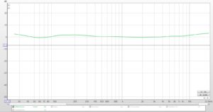
Below is the high resolution frequency response graph of a speaker mounted in a car. This is the left speaker and the microphone is in the driver’s listening position. This frequency response looks nothing like the frequency response of the speaker measured in an anechoic chamber, so the difference is the car. The car causes this comb filter. The car causes all of these peaks and dips.

If you’re used to using a 1/3 octave RTA, then you don’t see this comb filter easily. This is the same measurement displayed at 1/3 octave. Smoothing the graph this way is called “spectral smoothing” or “spectral averaging”. It just removes the narrow peaks and dips and looks a bit more like what we actually hear.

But what causes all these peaks and dips in the car?
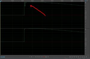
Here’s a hint. In the graph below, I’ve displayed 5 measurements of the same speaker. The measurements were made at 5 points in a 7” circle around the driver’s head position. They all look sort of similar, but they aren’t the same.

If you look closely, you’ll see that they look much more similar at low frequencies than they do at high frequencies. Below, I’ve zoomed in on the high frequency part of the response.

So, what gives?
Here’s the scoop. These peaks and dips that make up the comb filter are caused by the combining of direct sound from the speaker and reflections from all of the surfaces inside the car. Where you see a peak, the sound of the reflection is in phase with the direct sound of the speaker at the mic position and where you see dips, the sound of the reflection is out of phase with the direct sound from the speaker.
If you look more carefully, you’ll see that as frequency is increased, the differences between one microphone placement and another become more pronounced. One measurement has peaks at frequencies where other measurements have dips. So, the response depends on the placement of the microphone.
Below is the average of all 5 measurements at the 5 microphone positions. This is called “spatial averaging” and it looks more like what we hear than the spectral average. The reason that this better correlates to what we hear is because we constantly move our heads. Head movements help us localize sounds (determine where sound comes from) and they also smooth out all these narrow peaks and dips.

So, we hear the big dips at low frequencies because the wavelengths are too long to be affected by small changes in mic placement (or by small changes in the position of our head) but we don’t hear them as easily at high frequencies. For the purposes of this tip, we’re going to identify the transition from important enough to worry about to unimportant as 1 kHz. Above 1k, we don’t hear the comb but below 1k, we do.
Back to the comb. Peaks are caused by reflections in phase with the speaker and dips are caused by reflections out of phase with the speaker. What determines whether it’s a peak or a dip? What determines whether the reflection is in phase or out of phase?
Distance. At frequencies where the difference in distance is equal to ½ of the wavelength, we get a deep and narrow dip.
When two sources of the same sound at different distances from the mic (or listener) combine, they cause a comb filter.
That’s the rule. Those two sources can be two speakers or they can be two reflections or they can be a speaker and a reflection. If the comb is caused by a reflection, no amount of EQ or delay will improve it. Why? The reflection is caused by the sound from the speaker. We can’t affect that relationship–we can’t put a signal processor in between the speaker and the reflection caused by the sound of the speaker. All of that is another topic entirely. Today we’re focused on using delays.
We typically talk about comb filters as they relate to speakers and rooms. The comb filter determines how a room sounds and the design of listening rooms and concert halls is all about minimizing the comb or shaping it so it sounds pleasant. The frequency response part of the comb filter is tomorrow’s tech tip. Today we are going to talk about an aspect of comb filtering that gets less attention.
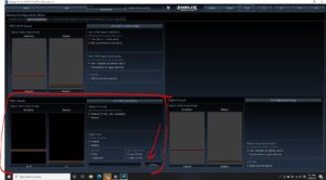
What happens when the front left and front right speakers are mounted at different distances? For this part, we’re going to use a simulation. If we use actual measurements, what we’re trying to see will be obscured by the comb caused by the reflections. We just want to see the relationship between the left and right speakers.
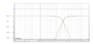
In the diagram below, we’ll look a two ideal speakers mounted in the doors (where the midbass or midrange speakers are usually mounted). These ideal speakers have flat frequency response from 20Hz to 20 kHz. That will make identifying the problem on which we are focused easier.
Below, we see the individual responses of the ideal left and right speakers. Remember, the image we hear in between, and specifically our center image, depends on our hearing the two speakers, playing together, in phase. Sounds that are recorded exactly the same in the left and right channels should seem to come from a point directly in between the two speakers–in the center of our “soundstage”.

But, phase is related to time, and time in an acoustic signal is related to distance because sound travels at a particular and constant speed.
In our car, the right and left speakers are not mounted equidistant from the listener and that creates a comb filter. The big graph below is the frequency response of the sum of the right and the left. That’s the frequency response of our center image.

Now, we have peaks and dips because the speakers aren’t equidistant. But, we have another problem. Everywhere there’s a dip, we hear the speakers out of phase. When two speakers are out of phase, there’s no center image. So, at 250 Hz, there’s no center—we hear the speaker locations instead. The same condition happens at every odd multiple of 250 Hz.
If you look carefully, you’ll see that the dips get narrower at higher frequencies. That makes them harder to hear. Also, the fact that we constantly move our heads makes what happens with phase above 1 kHz less important. What is important here is that at 250 Hz we have no center image. That frequency is right in the middle of the vocal range, and singers are often mixed so they are stage center.
The pathlength difference between the left speaker and the right speaker in this scenario is 28”. That’s pretty typical for door mounted mids. Before we had the ability to delay the signal to one speaker using a DSP, there were a couple of things we could do. One was to invert the polarity of one of the mids. Below is what happens if we do that.

We fix 250 Hz, but we destroy our midbass and we move the out of phase problem to 500Hz. That improves the placement of vocals, but doesn’t completely fix our system.
Another remedy is to move the speakers to the kick panels. We can never completely equalize the pathlengths, but we don’t have to. Remember, above 1k, we don’t really hear this problem. If we can move the comb so it starts above 1k, then we make a huge improvement. Below, we’ve moved these speakers to the kick panels and the pathlength difference is now 6” instead of 28”. The smaller the pathlength difference, the higher the frequency at which the comb filter begins.

Better, but not fixed. If you’ve ever listened to a car with kick panel speakers and thought it was great, that’s evidence that what happens above 1 kHz isn’t so important.
Now, what happens if we delay the left speaker by 2 mS, which corresponds to our 28” difference in distance?

There. Fixed. For a one-seat car, this eliminates the phase problem between the front speakers and ensures we have the center image we’re supposed to hear.
Never use delay and reverse the polarity of one of the mids at the same time. Delay completely fixes the phase problem and reversing the polarity with delay just screws things up.
So, left vs. right delay doesn’t affect the apparent location of the left or right speakers, but it does change what happens between them. For imaging, that’s a big deal.
Tomorrow, we’ll cover delays between tweeters, mids and subs. I’ll add a fourth part to this series that will cover all the ways we can measure this to ensure we’re setting this correctly.