
In part two, we discussed comb filtering and how it affects both frequency response and imaging. Comb filtering is caused when two sources of the same sound are different distances from the listener or the microphone. Distance is one cause of different phase.
When we have two speakers playing the same sound that are mounted at different distances from the listening position, that difference in distance causes the sources to be 180 degrees out of phase at a frequency at which the difference in distance is equal to half a wavelength.
Yesterday, we were primarily concerned with how the left and right speakers in a stereo system, in which the listener is off center, creates both frequency response and phase errors in the combined frequency response (which is our center image). Remember, where the two speakers are 180 degrees out of phase, we have a deep dip in the frequency response and no center image.
In every high performance car audio system, we use a combination of speakers to reproduce the full range of audible frequencies (20 Hz – 20 kHz). In some systems, that’s a combination of a subwoofer and two full range front speakers. In other, more complicated systems, the front speakers may be a combination of a midrange speaker and a tweeter. In a 3-way front speaker system, we use a midbass speaker (woofer), midrange speaker and a tweeter. In other systems…sigh…we don’t use tweeters.
There are significant benefits in systems that use several speakers, each playing band of frequencies for which they are optimized. Since this is a tech tip on crossovers and delays, we’ll forego the lengthy explanation about the many benefits and few detriments of crossovers.
The purpose of a crossover (a combination of a high pass filter and a low pass filter) is to divide the signals sent to the speakers in such a way that when the acoustic output of the combination of the speakers reaches our ears, we don’t hear the crossover. We should hear the combination as if it was a single speaker. This isn’t the mystery it may seem to be and once you understand it, the basics are just that—basics. They’re pretty simple.
I’ve been working on a crossover design for a project and it provides a good example.
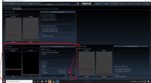
This passive crossover is designed to divide the signal between a 4” midrange and a tweeter. I’ve chosen about 2.7 kHz for the crossover frequency. Below, is the response of the tweeter and the tweeter with the high pass filter.

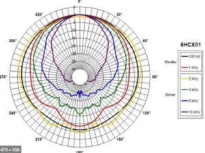
Next, is the midrange with its crossover. Because the listener will be about 30-degrees off axis from the midrange, I’ve chosen a curve measured about 30 degrees off axis on which to base this circuit.

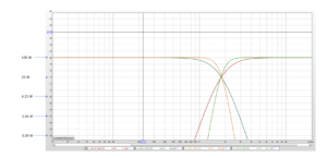
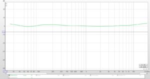
The objective of any crossover design is to use the filter to modify the acoustic output of the speaker so that the acoustic output of the speaker matches a target response. If we do that correctly, then the band of frequencies that both speakers play should sum flat. After some computer optimization help in choosing capacitors, inductors and resistors, the result of this one is pretty good. Here’s the predicted response of the system.

And below is a combination curve that shows all the parts at the same time.

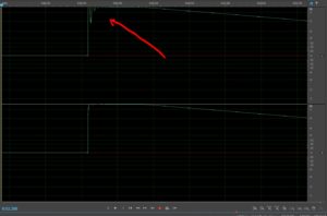
In this program, I can simulate the response of the crossover with the speakers at various distances from the measurement point that’s used to simulate the response. For the circuit above, I’ve input the distances from the mic location so that the sound of the speakers arrives at that point at the same time—I’ve delayed the tweeter a little bit to match the location of the midrange and the response at the crossover is pretty flat–that’s how it’s supposed to look.
Below is the same crossover circuit on the same speakers but with a distance error of about 4”.

And below is the same thing with a distance error of about 10”.

Notice that in both cases, this looks like the comb filter we talked about in part two. We don’t see the whole comb, because the two speakers only play the same thing in in the crossover region. In the first example, we see the left-most dip in the comb–the big one. We don’t see the higher frequency part because at high frequencies, the midrange doesn’t play.
In the second one, we’ve shifted the big dip in the comb to a lower frequency and we see the high frequency part of the comb in the crossover–the part where the dips and peaks are more narrow. We don’t see the big dip, because the tweeter doesn’t play at that frequency.
So, why does that happen? Phase. You’ve probably read or been told that crossovers shift phase and that’s one reason that they should be avoided. Since there’s really no possibility of a single speaker that plays the entire audible range with low distortion and similar dispersion at all frequencies, we’re stuck with them.
Here’s the rub. Crossovers do alter phase. However, phase in the acoustic signal from the speaker changes every time the acoustic output changes direction. That means that anywhere the speaker’s response isn’t flat, the phase changes, whether there’s a crossover attached or not. The low frequency roll off of your tweeter, even without a crossover changes the phase. For every 6 dB/octave of attenuation, phase changes by 45 degrees. No ifs ands or butts. That’s the rule.
What’s great about crossovers is that they give us tools to optimize the acoustic frequency and phase responses. The phase between two speakers determines how the sound from those two speakers will combine. When the phase is complementary, the sum of the output of the two speakers combines to produce more output. From an imaging perspective, that helps us hear the two speakers as one speaker. When our right and left speakers are in phase, we hear a center image. When a midrange and tweeter are in phase, we hear them as a single speaker.
So, when we apply high pass and low pass filters to speakers, we are trying to make the sum flat—we are trying to come up with filter shapes and filter phase that are complements, so that the sound we hear (or the mic hears) seems like it comes from one speaker with flat response.
Here are a couple of additional rules. 1) the phase of a low pass filter lags (is behind) the input of the filter, and 2) the phase of a high pass filter leads (is ahead of) the input to the filter. So, in a first order (6 dB/octave) crossover (as measured at the output of the speakers), the low pass filter is -45 degrees and the high pass filter is +45 degrees. The result is that the speakers are 90 degrees out of phase at all frequencies. The difference between -45 and +45 is 90 (-45-45) = 90.

Here is the same thing, viewed another way. The phase of the tweeter leads and the phase of the midrange lags. They are 90 degrees apart at every frequency.

If we choose higher order crossovers, the phase relationship changes. In a second order crossover, the low pass lags by 90 and the high pass leads by 90. The difference is 180 degrees. That means that the speakers are out of phase. At and around the crossover, that matters because both speakers play the same thing. If they are out of phase, that creates a dip in the frequency response and it also means that at those frequencies, we hear the locations of the two speakers rather than the combination as one speaker, just like when our right and left speakers are out of phase and we hear no center image.
Below is a mock up of a second order crossover.

Next, is the response of the sum of the two filters. Because these are second order (12dB/oct) filters, the speakers are 180 degrees out of phase. At the crossover, that’s a problem and it creates a big dip in the response.

If we reverse the polarity of the tweeter, the speakers are now phase. Because the crossover is designed so that both sides are -3dB at the crossover frequency, the sum includes a hump in the response rather than a dip. Adding two sine identical sine waves in phase gives us a gain of 6dB. Since they are both -3dB, that makes the hump in the response about +3dB at the crossover.

Enter Linkwitz Riley alignments. In LR filter, the circuit changes the shape of the output of the speakers compared to the Butterworth alignment. In a 4th order LR alignment, the speakers are at -6dB at the crossover and the shape of the rolloff has been changed (Q is 0.5 instead of 0.707). The additional 2 orders on the high and low pass add more phase shift. The result is that the low pass lags by 180 degrees and the high pass leads by 180 degrees. The difference is 360 degrees, which is effectively 0 degrees. The speakers are in phase and the response is flat with the speakers in the correct polarity as in the mockup below.


When you select a crossover frequency, slope and alignment in your DSP, you are selecting an electrical response that will be applied to the acoustic response of the speakers. The acoustic response is what matters. In order for the crossover to work properly, the sound of the speakers has to arrive at the listener or the mic at the same time. If it doesn’t, the delay between them is added to the phase of the speaker that’s furthest away and now our crossover doesn’t perform correctly.
Hey, wait! How does that work?
Let’s say we have two speakers playing 1 kHz sine waves that are connected in correct polarity, but the midrange is mounted 6.8″ farther away than the tweeter. The length of each 1 kHz wave is about 13.6”. If one of the sine waves comes from a speaker that’s 6.8” farther away, then that 6.8”, which is ½ the wavelength, is added to the phase and now the result is that the two speakers are 180 degrees out of phase at 1k.
Here’s what that looks like on an oscilloscope.

Now, as I add delay (or distance) to the tweeter to compensate for the shorter path length, the phase gradually shifts until I’ve added 0.5mS. At that point, they are in phase.


Delaying the tweeter to match the distance to the midrange puts them back in phase and now our crossover works the way it should.
So, getting the phase right between your tweeters and midranges, midranges and midbass is helpful in creating a system that doesn’t “rainbow” and in which all the sound comes from a point above the dashboard. Delay is one way that we can adjust phase.
But what about the sub? Why do I have to delay everything to match the sub? Why doesn’t the tape measure always generate the right results? How can I make the sub sound like it comes from the front?
We’ll save that one for the next tip. There are some other things to consider with subs.