
Lets say you park your car on a hill. Let’s also say it’s a standard transmission, and you leave it in gear. It should be there when you return, right? Sure. The transmission SHOULD hold it in place. But what if a mishap occurs? What if someone tries to parallel park behind you and bumps your car and the transmission pops out of gear? Your car rolls down the hill and crashes into a pole. Then what? Do you call the manufacturer of the car and expect them to cover it under warranty?
Good luck with that.
That’s what the parking brake is for. It’s a fail-safe. Does the existence of the parking brake adversely affect the performance of the car? Well, if you want to be nit-picky, I suppose it does. Removing it would remove a little weight which would increase the power to weight ratio of the car. Is that a meaningful enhancement in performance? Is the enhancement in performance worth the risk? If you’re not paying for the damage an unforeseen failure causes, then maybe so.
So, what does this have to do with tweeters? Keep reading.
First, let’s think for a minute about a tweeter’s job. It’s supposed to reproduce high frequencies. Making a tweeter that does that job well requires a bit of optimization. Since we don’t need a tweeter to make bass, we eliminate all the things that would be required to make bass because they are detrimental to high frequency performance. The two biggest detriments to making high frequencies are diaphragm diameter and weight–going forward, we’ll refer to weight as “mass”.
First, one of the rules for speakers is that for any given input power, excursion (how far the cone or dome has to move) is quadrupled for every halving of frequency. For example, if the cone is moving 1 mm at 100Hz, it has to move 4 mm at 50 Hz and 8 mm at 25Hz. Speakers designed to make bass have to move a long way. Speakers designed to make high frequencies don’t.
The voice coil is the part of the speaker that determines how far the motor can drive the diaphragm. Below is a picture of a subwoofer’s voice coil and a tweeter’s voice coil. It’s pretty easy to determine which one is designed to make bass and which one cannot make bass.The subwoofer’s voice coil is nearly 2″ long and the tweeter’s voice coil is about 1/32″ long. Applying a bass signal to the tweeter with enough power will cause it to try to move far past its limits and the tweeter will be damaged. The excursion limited (mechanical) power handling of the tweeter is MUCH lower than the subwoofer.

The amount of power that a speaker can handle is also determined by the voice coil’s ability to dissipate heat. The resistance of the coil determines how much current flows through it and that resistance turns some of the power into heat. The rest of the power is turned into motion. The ability of the coil to dissipate heat is determined, mostly, by its surface area. It’s pretty easy to see in the picture above which one is going to handle the most power.
So, what’s the difference between 100 watts at 50 Hz and 100 watts at 5 kHz? In terms of excursion, there’s a big difference. At 50 Hz the speaker has to move a lot farther. In terms of thermal power handling, not much, if we’re talking about test tones. But what about music?
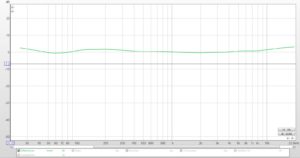
Below is the frequency response of a song we’ve all heard a thousand times: Hotel California. You can see that in the recording, there’s a lot more bass than there is information at high frequencies.

If we think about the distribution of energy in terms of amplifier power, things become a little clearer. In the picture below, I’ve indicated the amount of amplifier power necessary to reproduce this track. If your amplifier produces 100 watts at low frequencies, it only needs to be able to make about 6 watts between 1 kHz and 2.5 kHz to play this track. At really high frequencies, 1/10 of a watt is all that’s needed. So, no matter how powerful your amplifier is, when you listen to Hotel California, your amp doesn’t actually make much power at really high frequencies and that’s just fine for the little voice coil in the tweeter.

In a simple passive crossover, we use a capacitor to limit the amount of low frequencies that make it to the tweeter. This does two things: 1) it protects the tweeter from the application of too much power at low frequencies, and 2) it helps us shape the response of the tweeter to match the response of the midrange. Below is a picture of the frequency response of a tweeter with and without a capacitor.

It’s pretty easy to see that the low frequency output of the tweeter is reduced. We can change the value of the capacitor to change the frequency where the low frequency attenuation begins. A bigger cap begins to attenuate at a lower frequency.
The cap is placed in series with the tweeter, as in the diagram below,

Here’s how that works. As I mentioned above, the resistance of the voice coil determines how much current flows from the amp and through the speaker. A capacitor, simply stated, increases the resistance of the circuit at low frequencies. If the resistance of the circuit is increased, less current flows. The amplifier makes less power at frequencies where the resistance is higher.
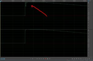
Below is a graph of the impedance curve of the tweeter with and without the cap. At low frequencies, the impedance is much higher.

Here’s how that affects the amount of power the amp produces. This shapes the frequency response and protects the tweeter.

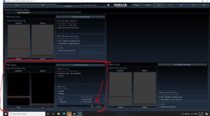
In an active system, we use a different means to shape the tweeter’s response and to remove bass from the signal. We put the high pass filter BEFORE the amplifier. This provides lots of benefits. We’re able to tune the system much more easily and we can implement nearly any filter, especially if we’re using a DSP. Below is what that circuit looks like–I’ve inserted an active filter before the amp and after the head unit (the signal source).

So, with the active filter, we shape the response of the tweeter as in the graph below. This is a 24dB/oct Linkwitz-Riley high pass filter at 2.5 kHz. Looks great.

We HOPE that nothing bad happens in the DSP or the amplifier, because anything that is produced INSIDE of those components AFTER the active filter will be passed straight to the tweeter. Turn on and turn off pops? Straight to the tweeter. Amplifier failure? Straight to the tweeter. Engine noise? Straight to the tweeter. An erroneous crossover or EQ setting in the DSP? Straight to the tweeter. If any of those erroneous signals make it to the tweeter, it’s likely to be damaged. This damage isn’t because the tweeter is defective. It’s because we applied too much voltage to the tweeter at frequencies it was never designed to handle. Should that be covered under warranty?
Does Ford give you a new car when you forget to set the parking brake?
But no one told you to set the parking brake.
There’s a simple parking brake for a tweeter and it’s a capacitor. Using a capacitor in an active system is a fail-safe. Above, I mentioned that a large cap begins to attenuate low frequency energy at a lower frequency. What if we choose a value that doesn’t affect the frequency response in the range of frequencies where we want the tweeter to play, but does limit exposure to errors that could damage the tweeter?
Below is the full circuit that includes the active filter and the protection capacitor.

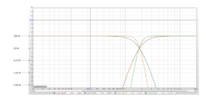
Now we’ve shaped the response with the active filter and protected the tweeter with a cap that has very little effect on the performance of the tweeter. You can see the difference between the frequency response with and without the cap below.

Is there a difference? Well, yes. There’s a tiny difference. About 1/2 a dB between 1.8 kHz and 2.5 kHz. IS that difference meaningful? Not if you consider that the response of the tweeter is attenuated by about 12dB at those frequencies. Does the cap have any affect at higher frequencies where the tweeter’s performance is important? No. None. Zilch. Nada.
In order for this to work we have to choose the value of the cap so its effects are outside the range of frequencies where we want only the active filter to affect the tweeter’s performance. For this tweeter, with a nominal impedance of 4 ohms, I’ve chosen a 68 uF cap. That’s a standard value and they’re available from Parts-express.com.
Finally, there are lots of different kinds of caps. Which one should you choose? Some people will tell you that you need one of those super-duper polypropylene caps and that you should NEVER use an electrolytic cap. For this application, that’s hogwash. For this exercise, I’ve used an electrolytic cap. Below are pictures of the two caps that are available from Parts Express. The first is an electrolytic. It’s costs about $1.75.

The second one is a polypropylene cap. It costs about $29.

Be sure to choose NON-POLAR caps. Those are the ones without the stripe and the (-).
Either one is fine for this application. Spending the additional $27.25 is, from a technical perspective, completely unnecessary. Get your car washed a couple of times instead or take your sweetie to a movie.
But…all tweeters need caps. They’re like parking brakes, not like condoms. Your enjoyment of your system won’t be hampered by the use of tweeter protection and you’ll never have to run to the store to get new tweeters before you can enjoy your system.