
There are lots of choices and even more opinions about which crossovers are the best. Arguments for and against the various slopes and alignments often include all kinds of crazy suppositions about the effects of phase shift, arguments that purport a gradual roll off to be better because they allow the speakers to “blend”. Some people advocate “brick wall” filters or even asymmetrical filters (12dB/octave high pass and 24dB/oct low pass). Some just choose crossover alignments because the name sounds exotic without any real understanding of the performance. I’m a big fan of Russian food, but that’s not a good reason to choose a Chebyshev alignment.
The simple explanation of crossovers is that they are filters we use to assign the duty of playing certain bands of frequencies to speakers best suited for the job. That transition should be inaudible. That means that we should hear the midrange and the tweeter, for example, as if they were one speaker. Basic crossover design assumes that the distance from each speaker to the listener or to the microphone is the same. Setting delays appropriately ensures this.
The suggestion that crossovers are bad because they shift phase is too simple to be useful. Yes, they shift phase. That’s how crossovers work. Phase in a low pass filter lags the input and phase in a high pass filter leads the input. A properly designed and executed crossover is simply an arrangement in which the amount by which the low pass lags and the high pass leads are complimentary and cause the sum of the sound of the two speakers to combine to hit the target.
When two identical sine waves (or music waveforms of any shape) are in phase, they combine to +6dB. When they are 180 degrees out of phase, they cancel each other. When they are 90 degrees out of phase, they combine to +3dB. All crossover alignments are efforts in managing the frequency response and the phase response to arrive at a target.
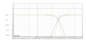
In figure 6, the high pass and low pass sections of a 6dB/octave crossover are displayed. The crossover point is 3kHz and both the high pass and the low pass sections are -3dB at 3kHz. The result of the 6dB crossover, if the frequency response of the speakers with the filters applied matches these targets and the sound from the speakers arrives at the same time will be flat response. That works because at the crossover point, both the high pass and the low pass are -3dB and the 90 degree phase relationship causes them to sum to +3dB.
Figure 6.
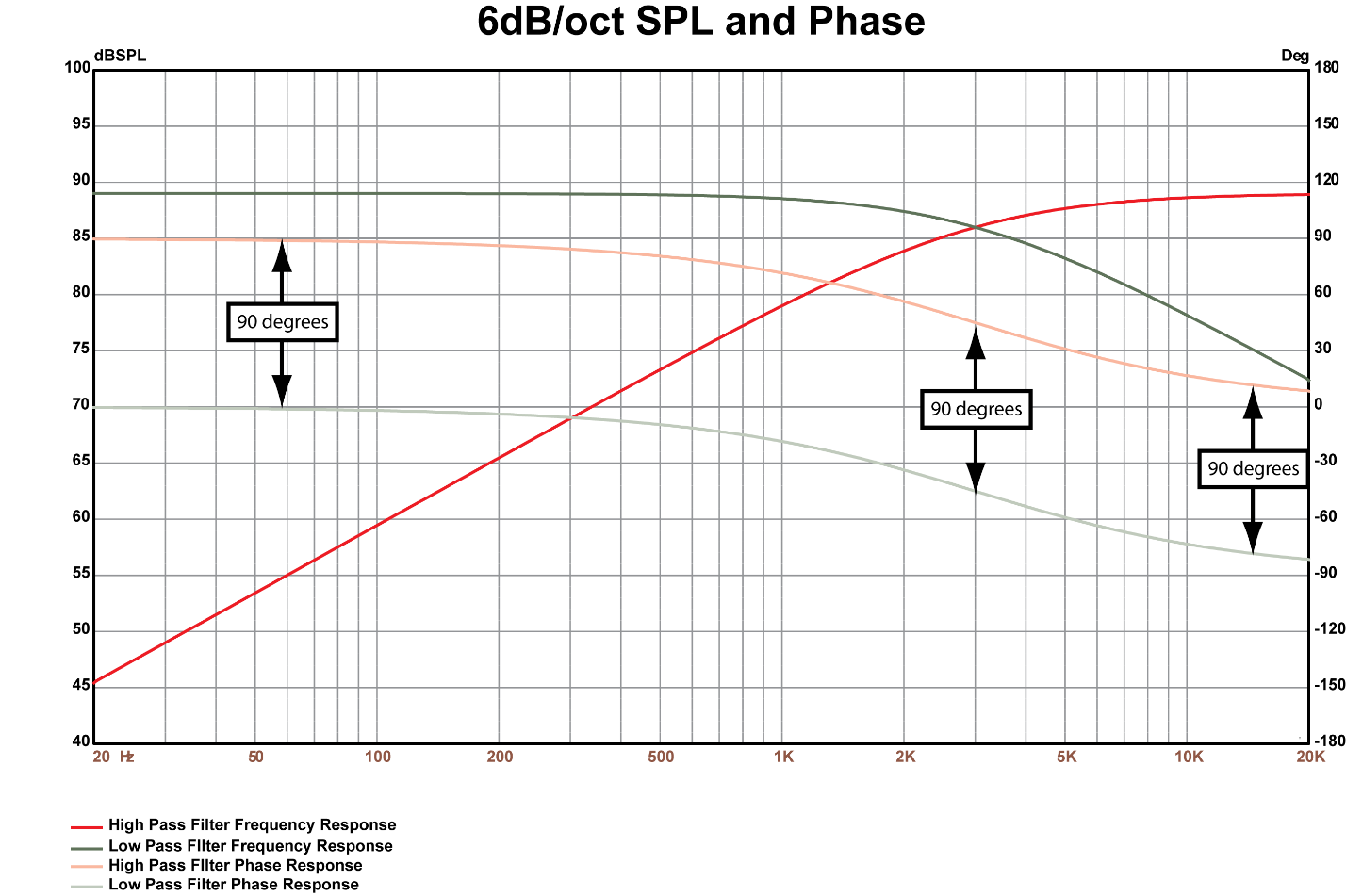
[Figure 6 Caption: 6dB/octave crossover frequency response and phase]
In figure 7, the high pass and low pass sections of a 12dB/octave crossover are shown. In this alignment (called Butterworth 6) the slopes are 12dB/octave and the high pass and low pass are each -6dB at the crossover frequency of 3kHz.
Figure 7
[Figure 7 Caption: 12dB/octave crossover frequency response and phase]

If we look carefully at the phase graphs of each, we see that the speakers are 180 degrees out of phase at all frequencies. At the crossover where the sound of both speakers play, this 180 degrees phase relationship will create a deep and narrow dip in the response at 3kHz. We can fix that hole by swapping the polarity of either the midrange or the tweeter.
In the Butterworth 3 alignment, in which both sides of the crossover are -3dB at the crossover, the response will include either a wider and deeper dip than the Butterworth 6 or a small +3dB hump in the response at the crossover when the polarity of one side is swapped (remember, in phase sums to +6dB and the speakers are both -3dB at the crossover—the 3dB hump is the rest of that 6dB).
Figure 8 shows the high pass and low pass sections of a Linkwitz-Riley 4 alignment. The slopes are 24dB/octave, the crossover is 3kHz and the high pass and low pass sections are both -6dB at the crossover frequency. The phase relationship between the HP and LP is 360 degrees, which is similar to 0 degrees. With the speakers connected in the proper polarity, the crossover sums flat.
Figure 8.
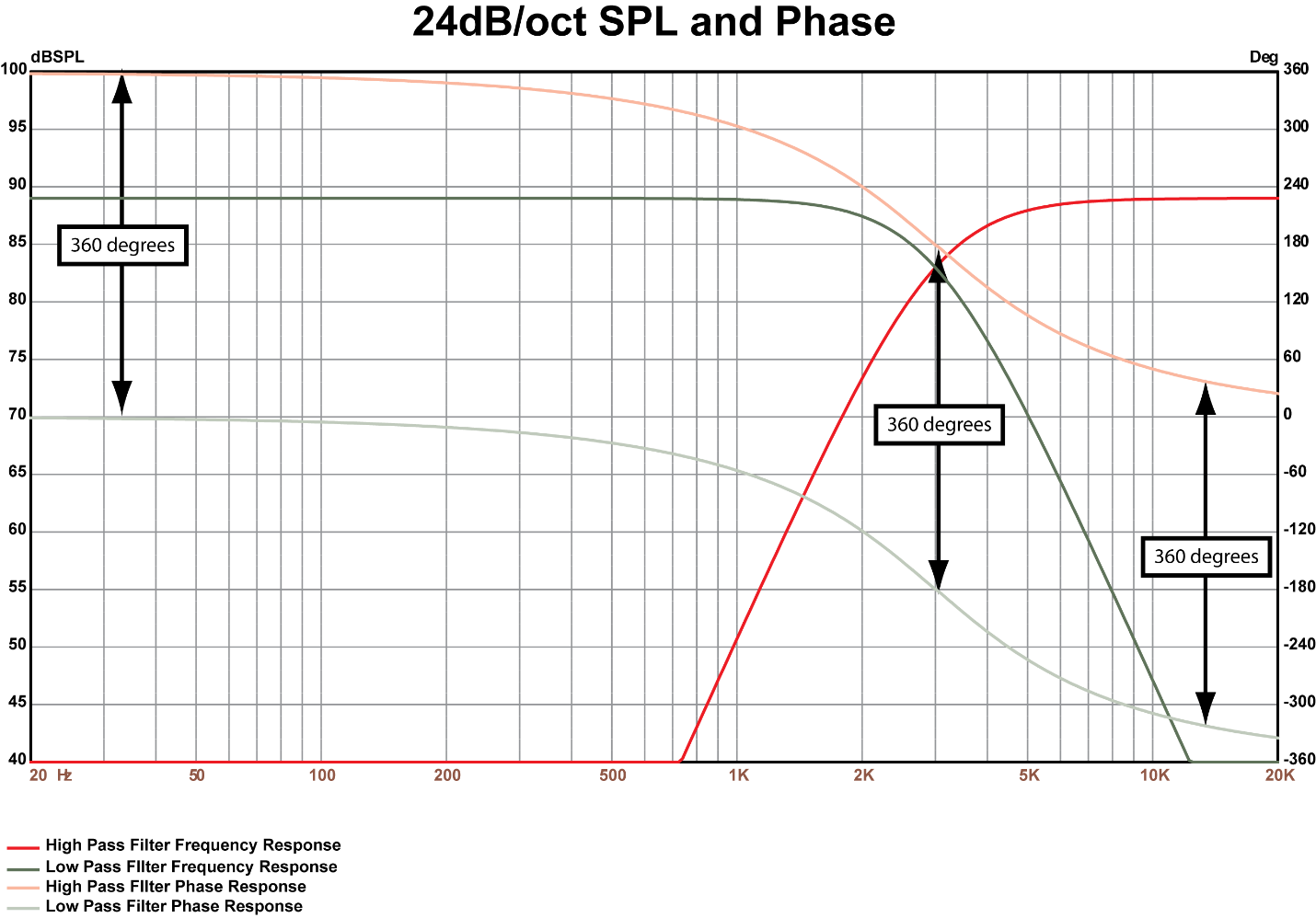
[Figure 8 Caption: 24dB/octave crossover frequency response and phase]
Remember, however, that the real crossover is the acoustic output of our speaker. So, in order to make these crossovers work the way they’re supposed to work, the output of the speakers have to match these slopes as closely as possible.
Let’s see what happens when we apply each of these to a real tweeter. Figure 9 is our 6dB/octave filter applied to the tweeter.
Figure 9.
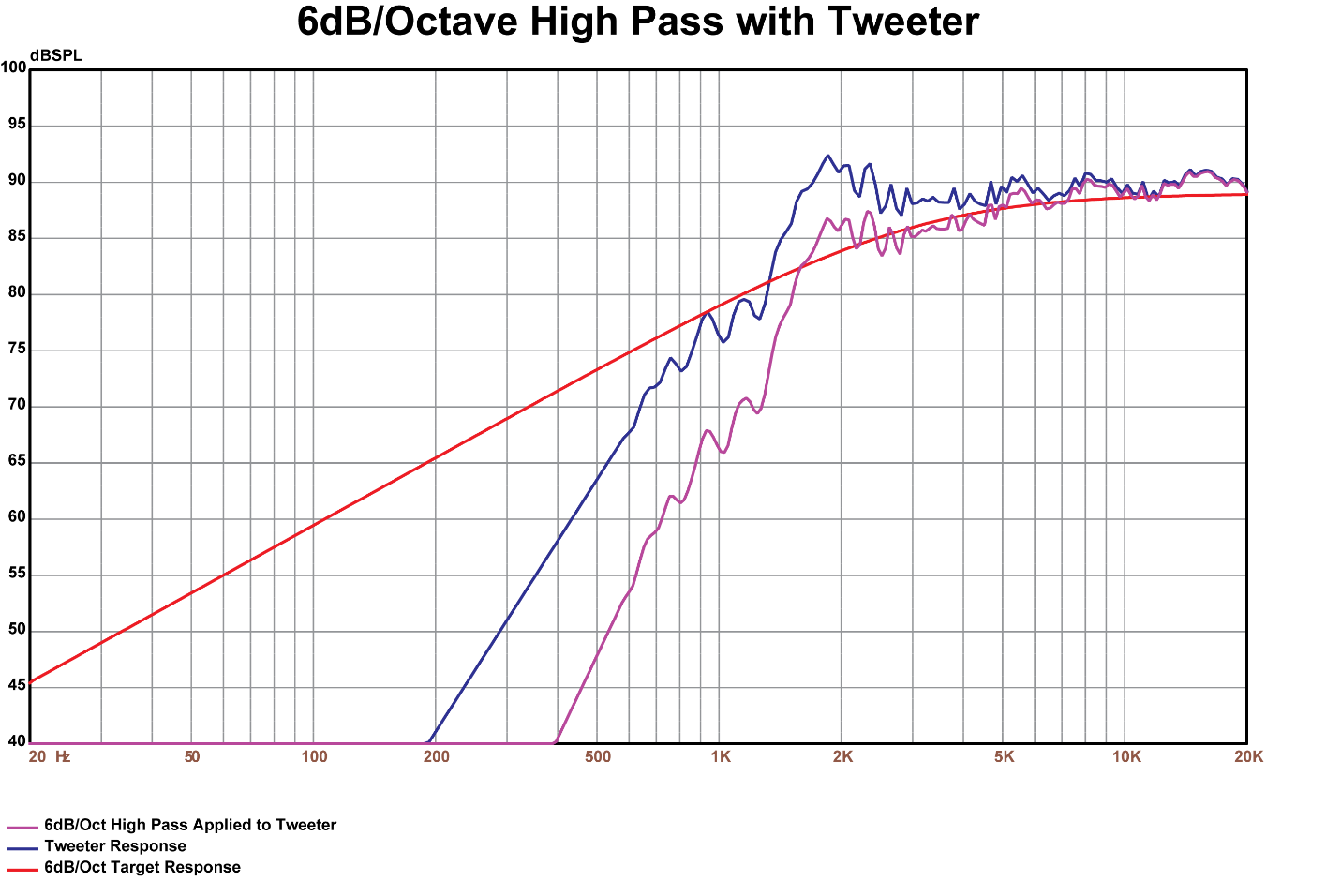
[Figure 9 Caption: 6dB/octave crossover applied to the tweeter]
It’s pretty easy to see that the acoustic output of the speaker isn’t very close to the target response.
Figure 10 is our 12dB/octave crossover applied to the same tweeter. This is better than the 6dB crossover, but there’s still room for improvement. Remember, if we use the 12dB slopes, we’ll have to reverse the polarity of the tweeter or the mid.
Figure 10.
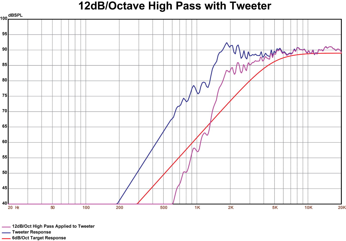
[Figure 10 Caption: 12dB/octave crossover applied to the tweeter]
Another thing to note in the two figures above is that the tweeter is still getting a lot of power below the crossover frequency around its resonance. Speakers make the most distortion at resonance, so it’s good audio engineering practice to minimize the amount of power we apply there.
In order to optimize both of these so our crossover works as it’s supposed to, we’ll need to apply some EQ to the tweeter channel to bring the frequency response in line with our target. That’s an extra step that takes time and we’re looking for the most predictable and speediest process that provides the desired result. What if there was a crossover that did the job without extra equalization of the individual channels?
Figure 11 shows the tweeter response before and after the 24dB/octave filter is applied. Because the filter is so steep, the tweeter’s output matches the target much more closely. No additional EQ is required to match the response to the target. Finally, at resonance, the tweeter gets almost no power and we’ve minimized distortion.
Figure 11.
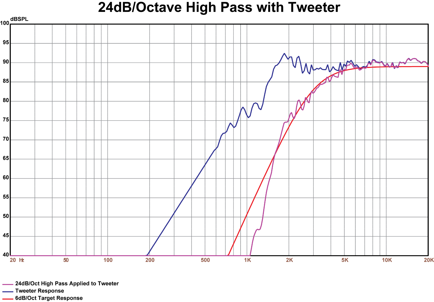
[Figure 11 Caption: 24dB/octave crossover applied to the tweeter]
Figure 12 shows the response of the midrange with its crossover, the tweeter with its crossover and the sum of this tweeter and midrange using the 24dB/octave Linkwitz-Riley alignment. In practice, you might want to correct some of the small peaks and dips below 500 Hz and tilt the high frequencies downward a little to match your in-car target curve with the EQ, but those are simple adjustments.
Figure 12.
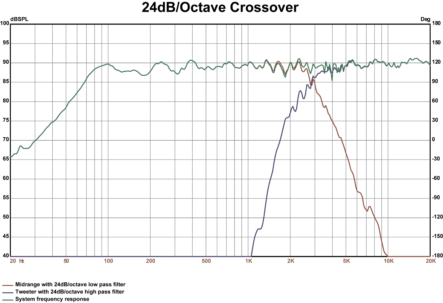
[Figure 12 Caption: 24dB/octave crossover]
The same set of graphs for the other alignments are shown in figures 13-16.
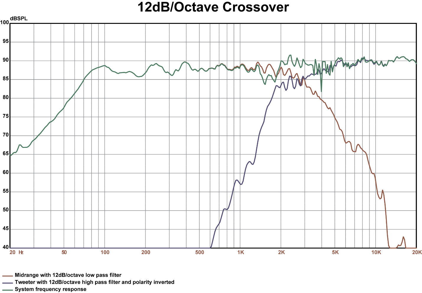
Figure 13 is the 6dB/octave crossover with both speakers connected in proper polarity. Figure 14 the 6dB/octave crossover with the tweeter polarity reversed. Figure 15 is the 12dB/octave crossover in proper polarity. Figure 16 is the 12dB/octave crossover with the polarity of the tweeter reversed. As you can see, all of these require additional work—either with the EQ or by swapping polarity or even both.
Figure 13.

[Figure 13 Caption: 6dB/octave crossover]
Figure 14.

[Figure 14 Caption: 6dB/octave crossover with tweeter polarity inverted]
Figure 15.
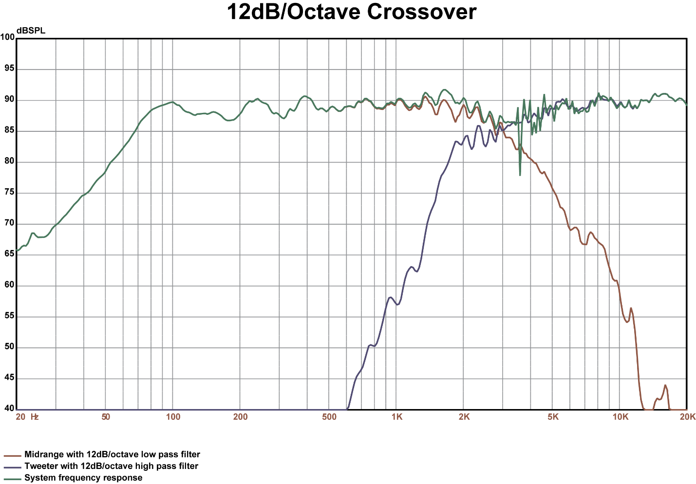
[Figure 15 Caption: 12dB/octave crossover]
Figure 16.
[Figure 16 Caption: 12dB/octave crossover with tweeter polarity inverted]
When choosing crossovers, the 24dB/octave Linkwitz-Riley type can save us time, minimize the complexity of the process and preserve and protect tweeters, too. For tuning customers’ cars in the bay, we need efficient processes that work. Many of us are both hobbyists and professionals. As hobbyists and enthusiasts, we sometimes get sidetracked by the idea that additional complexity is, by its nature, additional accuracy. Often that’s not the case. Sometimes the simplest way is also the best way. This article has presented two time and money saving procedures you can use in the bay to improve the performance of the systems you tune and improve your ability to tune cars efficiently and predictably.
Happy tuning!